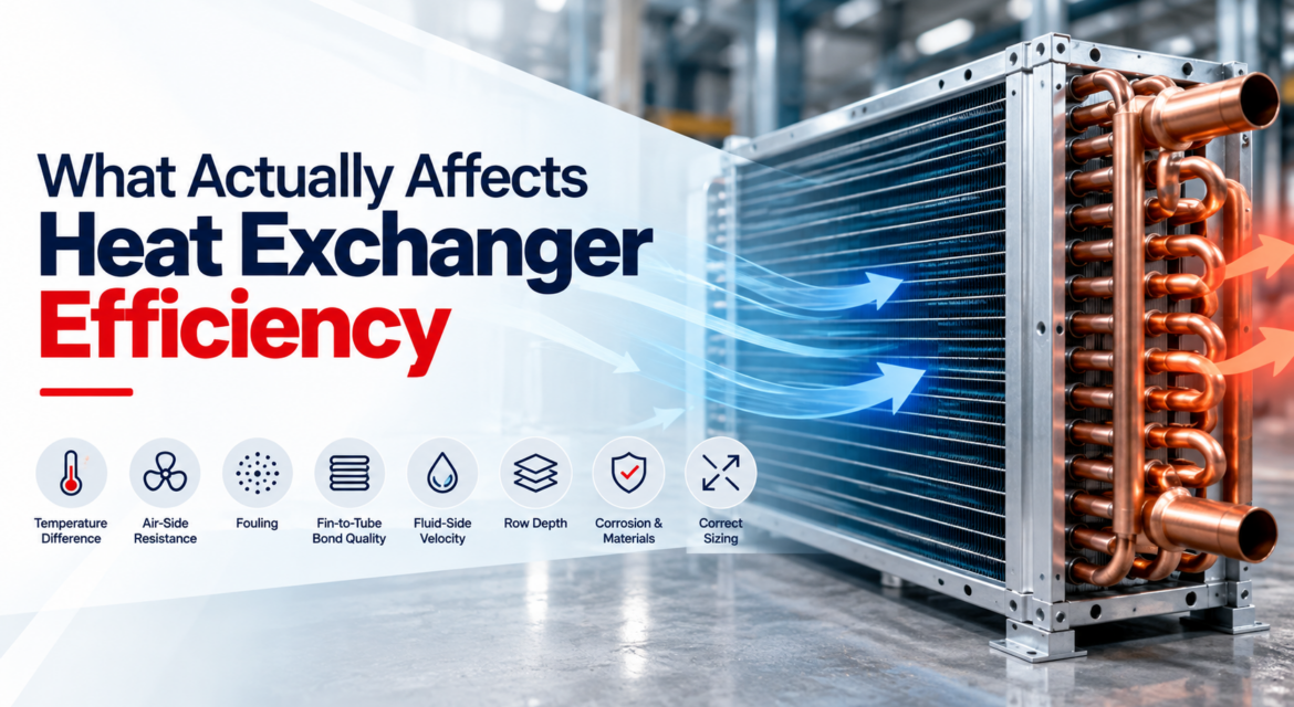
“Efficiency” is a slippery word in heat exchanger discussions, because it gets used for at least three different
things: how close the coil comes to the theoretical maximum heat transfer, how much fan or pump energy it
costs to move fluid through it, and how well it holds its performance over years of service.
A coil can be excellent at one and poor at another. The highest-effectiveness coil in a catalogue is frequently
the one with the highest pressure drop and the fastest fouling rate — meaning it is the most efficient on day
one and the least efficient by month eighteen.
Here is what genuinely moves each of the three, roughly in order of impact.
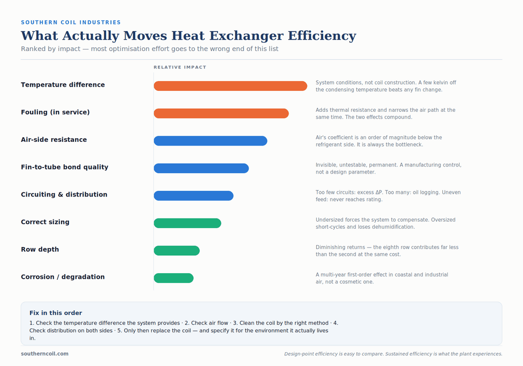
1. Temperature Difference — the Factor That Dwarfs the Others
Heat transfer is driven by temperature difference. Everything else in coil design is an attempt to make better
use of the temperature difference available.
This is why the largest efficiency gains usually come from system conditions rather than coil construction.
Reducing the condensing temperature of a refrigeration system by a few kelvin — through better condenser
sizing, cleaner coils or improved air flow — lowers compressor discharge pressure and reduces compressor
power draw across the whole operating envelope. That effect is far larger than anything achievable by
changing fin geometry.
The practical implication: before optimising a coil, check whether the system is giving the coil a fair
temperature difference to work with. A condenser recirculating its own discharge air because of poor
installation clearance is operating at an elevated ambient it was never designed for, and no coil specification
will fix that
2. Air-Side Resistance — Where the Bottleneck Almost Always Is
In an air-to-refrigerant coil, the air-side heat transfer coefficient is roughly an order of magnitude lower than
the refrigerant-side coefficient. The air side is the bottleneck, which is why the air side carries fins at all — the
fins are there to compensate for air’s poor heat transfer by adding surface area.
Three things determine air-side performance:
Air flow rate. Heat transfer rises with air velocity, but so does pressure drop, and pressure drop rises faster.
Fan power scales approximately with the cube of flow rate, so pushing more air through a coil to gain
capacity gets expensive very quickly. Doubling air flow does not double capacity; it may increase it by 60 to
70% while requiring roughly eight times the fan power.
Fin geometry. Louvred fin achieves a significantly higher air-side heat transfer coefficient than flat fin,
because each louvre interrupts the developing thermal boundary layer and restarts it. Wavy or zig-zag fin sits
between the two. The gain is real — but it comes with a proportional pressure-drop increase and a
substantial fouling penalty. See Article 1 for how to choose
Air distribution. A coil with air flowing unevenly across its face performs worse than its rating regardless of
how well it is built. High velocity through part of the face and stagnation elsewhere means part of the surface
does almost no work. This is an installation and equipment-design issue rather than a coil issue, and it is a
common cause of “the coil isn’t performing” complaints that turn out not to be about the coil.
3. Fouling — the Largest Long-Term Effect
Everything above concerns a clean coil. In service, fouling is usually the dominant factor.
A dust layer on the fin surface does two things simultaneously: it adds thermal resistance, and it narrows the
air passage, reducing flow. The two effects compound. A coil that has lost 30% of its air flow to fin blockage
and gained a thermal barrier at the same time may be delivering little more than half its rated capacity.
The relationship between fin density and fouling rate is not linear. Closely spaced fins do not just collect
proportionally more debris — they bridge. Once a fibre or particle spans the gap between two fins it becomes
a collection point, and blockage accelerates. This is the mechanism that makes high-density coils in dirty
environments fail so much faster than their fin density alone would suggest.
Practical consequences:
- Fin density selection should be made for the environment, not the catalogue duty (Article 1 has the
table) - Filtration upstream of an indoor coil is almost always cheaper than the capacity lost without it
- Cleaning intervals should be set by inspection, not by calendar alone (Article 5)
4. Fin-to-Tube Bond Quality
This one is invisible and therefore worth stating plainly.
The fin is only useful if heat can travel from the tube into it. That path runs through the mechanical contact
between the tube outer wall and the fin collar, created when the tube is expanded after assembly. If
expansion is inadequate, a microscopic air gap remains at every single fin — and air is an excellent insulator.
A coil with poor expansion looks identical to a good one, passes leak testing without issue, and simply delivers
less than its rated capacity, permanently and undiagnosably. There is no field test for it.
This is a manufacturing process control, not a design parameter, and it is one of the strongest arguments for
caring about how a coil is made rather than only what it is made of. See Article 3.
5. Fluid-Side Velocity and Circuiting
On the refrigerant or water side, the goal is turbulent flow at a velocity high enough for good heat transfer
but low enough to keep pressure drop acceptable — and, in refrigerant systems, high enough to carry oil back
to the compressor.
Circuiting is what sets this. Too few parallel circuits produces excessive pressure drop, which on the
evaporator side directly reduces suction pressure and system capacity. Too many circuits drops velocity,
which reduces the heat transfer coefficient and risks oil logging in the coil
Inner-grooved tube improves this side of the equation without changing the circuiting: the internal helical
grooves increase wetted area and promote turbulence at the tube wall, raising the in-tube coefficient. Where
refrigerant-side performance is the constraint and the envelope is fixed, inner-grooved tube is often the most
effective single change available.
Uneven distribution deserves particular mention. In a multi-circuit DX evaporator, a distributor that feeds
circuits unevenly starves some and floods others. The starved circuits run dry with high superheat,
contributing little; the flooded ones risk liquid return. Rated capacity is never reached, and the fault is
frequently misdiagnosed as a charge or valve problem.
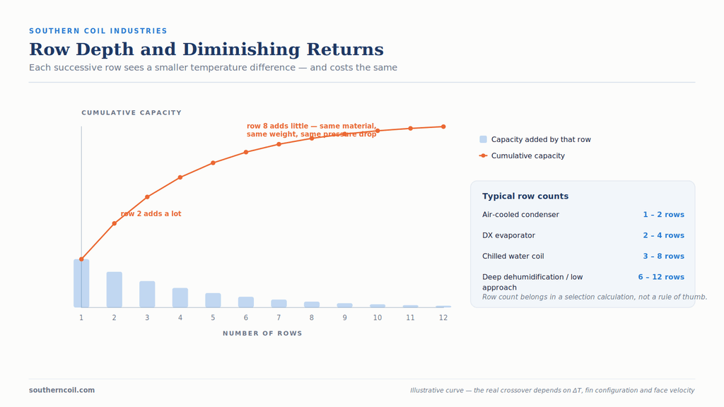
6. Row Depth and Diminishing Returns
Adding rows adds surface area, but each successive row sees a smaller temperature difference than the one
before it, because the air has already been partially conditioned. The result is diminishing returns: the fourth
row contributes noticeably less than the second, and the eighth less than the fourth, while costing the same
in material, weight and air-side pressure drop.
There is a point beyond which adding rows costs more in fan energy than it recovers in capacity. Where that
point falls depends on the temperature difference, the fin configuration and the air velocity — which is why
row count should come out of a selection calculation rather than a rule of thumb.
7. Corrosion and Material Degradation
Corrosion reduces efficiency in three ways: corrosion product on the fin surface acts as a thermal barrier; fin
material loss reduces effective surface area; and corrosion at the fin-to-tube interface degrades the bond
described in section 4.
In coastal and industrial environments this is a first-order performance issue on a multi-year view, not a
cosmetic one. See Article 7.
8. Correct Sizing
An undersized coil cannot reach the required duty and forces the rest of the system to compensate — longer
run times, elevated condensing temperature, higher compressor power.
An oversized coil is a subtler problem. It costs more, weighs more, takes more space and carries higher airside pressure drop. On a DX evaporator, significant oversizing can cause control problems: the coil satisfies
the load too quickly, the system short-cycles, and dehumidification suffers because the coil never runs long
enough to remove moisture. In a humid climate this produces a space that meets its temperature setpoint
and still feels uncomfortable.
“Bigger is safer” is not a reliable heuristic for coil selection.
What This Means in Practice
If you are trying to improve the efficiency of an existing installation, work in this order:
- Check the temperature difference the system is providing. Recirculation, blocked discharge, high
ambient from poor siting. - Check air flow. Filters, fan condition, belt tension, damper position, obstruction.
- Clean the coil properly — using a method appropriate to the fin and coating (Article 5).
- Check for uneven distribution on both air and fluid sides.
- Only then consider replacing the coil, and if you do, specify it for the environment it will actually live in
rather than the one in the original design brief
And if you are specifying a new coil, remember that the highest-effectiveness option in the catalogue is rarely
the one that will still be performing well in five years. Design-point efficiency is easy to compare on a
datasheet. Sustained efficiency is what the plant actually experiences.
Looking at a coil that isn’t performing?
Southern Coil Industries designs customised fin-and-tube heat exchangers around real operating conditions, including the environment the coil has to survive. Send us the conditions and we will tell you what we would change.